Get the stl model files Here.
You can order the parts from here, in a variety of materials.
Here are pictures of the part files, with their names.
Step 1
You will need two of these. Check the fit of the Yoke T and Yoke Extend, and trim if necessary to achieve a tight fit and a straight part. Separate the parts, put glue on both, and fit them back together. Wipe off any excess glue, and allow to dry thoroughly, possibly overnight, depending on the glue. I used "household cement". Despite the tight fit of the parts, gluing really is necessary. There's quite a bit of bending load on it. Not gluing will allow too much flex, and it really needs to be stiff.
Step 2
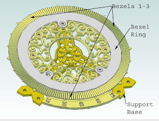
Look on the back of bezels 1 and 2, and find the index marks. Piece them together, as shown in the figure, then turn the grouping right-side-up.
Step 3
Slip the bezel ring screws (csink head) through the bezel ring, and loosely thread into the support base. Make sure the notch in the support base is oriented as shown in the figure.
Step 4
Piece together and slip Dome Capture Segments between the Support Base and Bezel Ring, as shown. The Support Base should fit into notches in the Dome Capture. Do not tighten the screws yet.
Step 5
Carefully turn the assembly over, and slip the Bezel sections under the Bezel Ring. The Bezel Ring will lock into the groove in the Bezel segments. Tighten all three screws until snug.
Step 6
These are the voyages of...
Fit the Mount Extensions onto the Support Base. Lock them together using the Support Bushings, as shown. Both Hi bushings go on one Extension, and Lo's on the other. Either way is fine. Make sure to use the correct length screw, and slip an angle roller under each screw. Slip a Scale Clip into place on each before tightening the screws. Leave the screws out or very loose on one side for now.
Step 7
Push Knob Bushing all the way into the knob until seated. A very small amount of the bushing should show through the bottom.
Pus the Arm Pin all the way into the Arm. Push the Arm Bushing onto the part of the Arm Pin that extends through the bottom. The Arm Bushing should contact the bottom of the Arm.
Step 8
Insert the Yoke Pin into the Arm until flush. Insert the Arm Pin into the hole in the center of the support base. Push the Gear Blank onto the Arm Pin, then secure into place with the Key.
Step 9
Assemble Yokes, et all onto the Yoke Pin, as shown in the picture. The Angle Rollers create a v-track for the inside of the Scotch Yokes. Tighten the Acorn Nut.
Step 10
Slide the Zero Scales onto the Yoke arms, and secure each with a Zero screw. Lay the lower Yoke into the Low Bushings, and secure with Angle Rollers and Low Bushing Screws. The Rollers and Bushings create a v-track for the Yoke to slide in. Secure the higher Yoke in the same manner, on the High Bushings.
Step 11
Align the Dome notches with the assembly, slip it into the Dome Capture Ring, and rotate it clockwise until it stops. I found it helpful to line up the screw holes first, then look at the notch that lets it fit over the support base/mount extension frame. Then clock it to the other edge of that notch, carefully push the dome edge into the slot, and clock it back until the holes line up again. I found it to be tricky, and might try wetting the edge lightly with water next time, to slightly lub it. Insert the Dome Screw to secure the dome in place.
All Done! Now wasn't that easy? No? Well, then doesn't it look cool?


 Make Magazine


