Sunday, November 17, 2013

Harmonic Transformer for the Classroom

Treat yourself and your classroom to a machine that shows you how Sine and Cosine relate to angles.  Get the stl model files Here, or check them out in Onshape, where you can make mods, if you want.


How to use: 
Use the knob to rotate the arm to an angle. Read the value on the Sine and Cosine scales. Sine and Cosine values are given for a circle with a radius of 1, which is also called a "unit" circle. To obtain lengths for a circle with a radius other than one, multiply the reading from the machine by the desired radius.


Sine and cosine are trigonometric functions of an angle, defined by using right triangles. In the animation above and the figure below, a right triangle has been drawn on top of the Harmonic Transformer. The angle below is set to 30°. The hypotenuse is the radius of the circle, shown as a green line. The hypotenuse/radius is drawn from the arm's pivot center to the center of the knob, where the yoke pin is. The blue horizontal line is the "adjacent" side of the triangle, and the magenta vertical line is the "opposite" side. Notice that the blue side is the same length as the reading on the cosine scale. Similarly, the magenta side is the same length as the reading on the sine scale.


Assembly Instructions
Step 1
Print and clean up the five model files, shown below. These are sized to fit the print volume of the MAKERBOT® REPLICATOR 2®: 11.2L x 6.1W x 6H. The dome is optional, but adds character and protects the "key" nut. Note that the files with "-raft" in the name need to be printed with a support raft. The other model files do not require a raft.


Step 2

Slip the bezel ring screws (csink head) through the bezel ring, and loosely thread into the support base. Make sure the notch in the support base is oriented as shown in the figure.

Step 3

Piece together and slip Dome Capture Segments between the Support Base and Bezel Ring, as shown. The Support Base should fit into notches in the Dome Capture. Do not tighten the screws yet.

Step 4


Carefully turn the assembly over, and slip the Bezel sections under the Bezel Ring. The Bezel Ring will lock into the groove in the Bezel segments. Tighten all three screws until snug.

Step 5
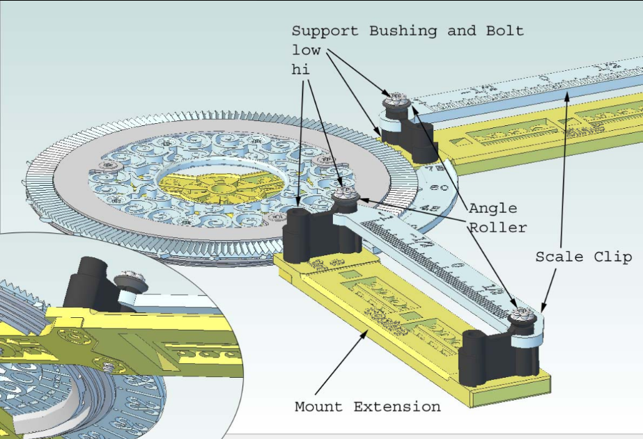

Fit the Mount Extensions onto the Support Base, taking care to put the Sine and Cosine in the proper locations. Lock them together using the Support Bushings, as shown. Both Hi bushings go on one Extension, and Lo's on the other. Either way is fine. Make sure to use the correct length screw, and slip an angle roller under each screw. Slip a Scale Clip into place on each before tightening the screws. Leave the screws out or very loose on one side for now.

Step 6

Push Knob Bushing all the way into the knob until seated. A very small amount of the bushing should show through the bottom.

Push the Arm Pin all the way into the Arm. Push the Arm Bushing onto the part of the Arm Pin that extends through the bottom. The Arm Bushing should contact the bottom of the Arm.

Step 7

Insert the Yoke Pin into the Arm until flush. Insert the Arm Pin into the hole in the center of the support base. Push the Gear Blank onto the Arm Pin, then secure into place with the Key, either the Rounded or Heart version.

Step 8

Assemble Yokes, et all onto the Yoke Pin, as shown in the picture. The Angle Rollers create a v-track for the inside of the Scotch Yokes. Tighten the Acorn Nut.

Step 9

Slide the Zero Scales onto the Yoke arms, and secure each with a Zero screw, adjusting them to point exactly at the 1 and 0 when at the extents of travel. Lay the lower Yoke into the Low Bushings, and secure with Angle Rollers and Low Bushing Screws. The Rollers and Bushings create a v-track for the Yoke to slide in. Secure the higher Yoke in the same manner, on the High Bushings.

Step 10


Align the Dome notches with the assembly, slip it into the Dome Capture Ring, and rotate it clockwise until it stops. I found it helpful to line up the screw holes first, then look at the notch that lets it fit over the support base/mount extension frame. Then clock it to the other edge of that notch, carefully push the dome edge into the slot, and clock it back until the holes line up again. I found it to be tricky, and might try wetting the edge lightly with water next time, to slightly lube it. Insert the Dome Screw to secure the dome in place.


All Done! Now start reading the sines and cosines of those angles!

My Printer in Action

I have one of the original Up! printers. Here are some photos, and notes on how I have it set up.

The print table has a bumpy surface (paint from the factory), and is covered with kapton tape. Prior to printing, I give the surface a quick wipe-down with acetone (fingernail polish remover) to clean the surface. This has been working well for me. The part clings to the table while printing, then peels off fairly easily with a spatula.

I made an enclosure out of an old cardboard box, tape, and a sheet of acrylic that slides across the front as a door. There is an opening in the top with an air conditioner filter covering it. The enclosure keeps the machine warm, which improves print quality. It also makes it quieter. The filter keeps down the aroma of melted PVC.


The door is off in the video below. It is very quiet when the door is on.


When the part breaks free from the table during the print, the results are pretty disastrous.


Sunday, July 7, 2013

Convert Raster graphic into a Vector graphic for laser cutting with Retina Engrave

Why I need a vector graphic: For laser cutting with my Full Spectrum Laser, the preferable way is to create a vector graphic. The most convenient way I have discovered so far is to work on the image with Inkscape before "printing" to the Retina Engrave "printer", which is the program that controls the laser cutter.

Here's how I got a raster image from Photoshop converted into an Inkscape vector graphic:

  1. To make strong outline vectors, draw filled shapes in Photoshop. The vectors will be outlines of these shapes. Crisp up the edges by using Threshold or sharpen masks. Print to a PDF file via cute pdf. If layers are to be preserved, print each layer separately.
  2. Open the first pdf in Inkscape. For multiple layers, import the other pdf's. Align them and move each to a separate layer.
  3. For each layer, select the imported image, which is a single box on the screen. Right-click and select "ungroup". Repeat this until "ungroup" is no longer available, probably 3 times.
  4. Select the  image, then: Click Path > Trace Bitmap > Colors, Stack scans, Remove background > Update > Ok. To verify it worked, you can click Edit, and it should say "Undo: Trace Bitmap". If it doesn't say this, then you may not have "ungrouped" enough times.
  5. Click to select the object, which will actually be the trace, and move it to a new layer. It will look the same as the original image. Hide the layer with the original. Click Shift+Ctrl+F to open the fill/stroke paint/stroke style menu. Select the trace object. Click the "Fill" tab, and click the "X" button. The graphic will disappear. Click the "Stroke paint" tab, and click the "flat color" button. Now you will see outlines. Select desired color. If "printing" to Retina Engrave for laser cutting, to prevent the vector from show up in the "raster" tab, click the "Stroke style" tab, and enter .1 pixel for the width.
  6. "Ungroup" the object once again. Now there will be about seven copies, varied slightly in darkness and size. Delete all but the most desirable one. To do this, I drag one to the side, and delete. Repeat until dragging reveals that there are no others left, then undo the last move. Note: If the original image was not one solid color, these seven layers of lines will be contours around changes in colors. In that case, keep however many vectors you like. I kept two layers for the wheat graphic below.
  7. Repeat for each separate layer. Color the layers a different color for each unique laser power/speed setting desired, choosing from the six main colors & complements: red, green, blue, cyan, magenta, yellow. Black may also be used, but is best reserved for raster images.
  8. To make a raster image also, either fill a shape or outline with more than .1 pixel thickness. Make sure there is a raster dot (even a white one will do) at the upper left of the page, so that the raster image will align properly with the vector image in Retina Engrave.  In Retina Engrave, checking "Ignore Raster" then printing from Inkscape will load in the vector data without updating the raster data. Works the same way with "Ignore All Vector". This gives nice control over what is in the raster and vector images.
Add any text or features desired, then "print" to Retina Engrave, and you're ready for some laser cutting! The settings in the photo below worked well for cardboard, if it lays flat on the table. If it curls up, the cut may not go all of the way through.

Photoshop image
Converted Photoshop layers, plus text and a graphic

Settings for laser cutting cardboard, test case before trying on wood. Cutting paths are color-coded and assigned an order, speed, and power. The Magenta speed was changed to 100 before cutting was started. 

Burning the graphic. This scorched the top layer without actually cutting.

The laser actually caused an orange flame to briefly appear while cutting. The cardboard shifted midway through the cut, because of the vent fan. Next time I will tape it down before starting a cut. 

The cardboard test cut being tried out. Now my measuring cup and spoon collection will stay put in the drawer.


Wednesday, August 1, 2012

Tipi, Teepee, Tepee

Here's what I've been doing all spring and half the summer in my free time: making a tipi! My daughter in the back is eight years old, and is sitting on a deflated air mattress; the cloth in the foreground is the edge of the door opening.


Since I haven't taken the time to write even one blog entry on it, I'll try and capture the story now, starting with this post. It all started when we were wanting to plan a camping trip for the summer. Our tent is more complicated to set up than we would like, and is nothing special. We found a Tentipi online, and thought it was really nice; well, until we found out that they don't sell them in the USA, and besides that they're very expensive. The main thing about them seems that they are a tipi made with a single center pole, rather than the 17 or so poles of a traditional tipi, and the outer shell goes up very quickly. Clearly the next best option was to try to build our own.

   That put us on the path of researching tipis. It just so happens that tipis are fascinating. There's a lot more to them than it seems at first glance. There's the inner wall, that insulates them. You can light a fire inside, something that was never possible in any tent I have owned. They have big smoke flaps with poles to maneuver them around and control the air flow vs rain. And they are stitched together up the front with those nice wooden stitch pins.

   In the end, I would be happy with nothing less than a traditional tipi cover and inner wall design, but I had to convert it to use a single, collapsible pole so it will fit in the car. This required a special design that made my 3d printer and Alibre modeling tool just the thing I needed to achieve it with. It's standing in my back yard right now, waiting to be packed up and taken to a campground in a weekend or two. It did not cost less than the Tentipi in the end, but I sewed every bit of it, made it be just how I wanted it, and I also have a new sewing machine. It is also very pleasant to sit in. :)

Note: while technically the single-pole design makes this more of a "bell tent", the canvas is a traditional tipi design, and would work equally well attached to a traditional 17 pole tipi structure. Also, the black nylon webbing straps running from the top of the pole to the ground act like poles, although not as rigid. I continue to think of it as a tipi, and choose to refer to it as such.


Wednesday, January 25, 2012

Garland attached to Brick

This post isn't exactly timely, but you'll have plenty of time to prepare for next Christmas. :)  I bought garlands to hang on the doorway Christmas-before-last. Then I looked for hangars to let me hang it on my brick home. Guess what? I couldn't find anything!

I needed something:
  • Easy to use
  • Not damaging to the brick
  • Attractive or subtle enough to look ok when the garland wasn't up
 Here is what I came up with:
3D print a set of clips (file is here on thingiverse, and on Shapeways), paint them black, stick them to the brick with sugru, and use paracord to tie the garland to the brick. It works like a charm!

To attach with sugru, sofen up a piece and work it into the grooves in the clip base, making sure it comes through the holes also. Push onto the brick, making sure it gets a good bond. Also work some sugru over the lip on the top edge of the clip base.

To attach shock cord, tie a simple knot in both ends of the cord. Slip one end through the large hole, then push into the slot. Pull on the cord until the knot bumps against the clip. Loop the cord around the garland, then wind the cord around the clip and into any available clip groove, or even into two.

 
Grooves on the base of the clip grip the sugru for a good strong bond.
Holes through the clip give even more hold for the sugru. The clip's shape is both fancy and practical, giving multiple ways to attach the shock cord securely, even without seeing what you're doing.

A clip attached to the brick with sugru.
Several clips sugrued to the face of the brick arch on our front porch.
Paracord, looped through the clip, like it would be when holding the garland.
Garland attached to the house with shock cord, sugru, and my clip.

Friday, December 30, 2011

Dropper Caps for Extract Bottles

Two of the four droppers I bought from KAF
 I got a four-pack of dropper lids for my citrus oils, because they are so strong you measure them in drops. Unfortunately, they only fit on the amber bottles, like the butterscotch bottle in the photo below.

Not being in a mood to be denied, I decided to pull the dropper out of the original cap, and make a cap to fit the clear, small mouth bottles. Using Alibre and calipers, it was easier than I had hoped, and also fit the McCormic bottles from the grocery store! Hurrah!

Orange oil with dropper, and three more caps I printed.
I went back and added some texture details to make the cap easier to turn, and more attractive. I decided to offer the model for free at Thingiverse, and the caps for sale on Shapeways at my store's kitchen section. They are more expensive than I would like, but perhaps worth a splurge if you frequently use extracts or oils in this kind of bottle. Either way, you'll need to purchase the droppers.

While Shapeways says that the plastic is not food safe, the cap doesn't touch the extracts. The black rubber on the dropper acts as a gasket/seal, and serves as a barrier between the cap and the bottle. If this makes you uncomfortable, then I suggest not getting them. Personally, I am comfortable that it is safe.
Variety of bottles with and without droppers.
McCormic bottle with and without dropper.

Filament Guide

The feed motor on my Up! printer failed a while back, and I have been living with a duck tape repair. Catching my breath after Christmas festivities, I decided it was high time to make a proper fix.

The feed motor is not needed, as the nozzle feed is strong enough to pull the filament from the spool unassisted. After first trying to modify someone else's model in Sketchup, and getting frustrated with the lack of associativity, I used Alibre instead. I sure wish I could find a way to import an stl for free, so I could trace off of the existing model, but instead I grabbed my calipers and started measuring.

It's pretty simple. Slip the filament in through the end, no need to pull it out of the nozzle, and the guide keeps the filament in check as it comes off the spool. While lacking frills, it works and looks better than tape. Model available at Thingiverse.