Thursday, November 21, 2013

Tipi pole and hat system

Here is my first follow-up on my tipi post. As I said in that first post, I decided to make a traditional tipi cover, based on instructions in the book "The Indian Tipi", but replace the traditional 17 wooden pole system with a single aluminum center pole to carry the weight of the tipi cover, and 1" nylon webbing serving as guy wires and "poles" for the tipi cover. In the spirit of being pack-able in a car, the pole is made of 2' sections, each having an additional 6" taper for slipping them together. In the photos below, you can see the black webbing "poles" and the sectioned 16' aluminum sch 40 pole.


The above views are looking up through the smoke flaps, which allow venting of smoke from a fire inside the tipi. We did try an open fire inside, but it was unfortunately smokey, and we were worried about CO poisoning. We now have a battery-powered CO detector. That also puts a portable wood-burning stove, preferably rocket-mass-heater style, onto our list of things to explore.


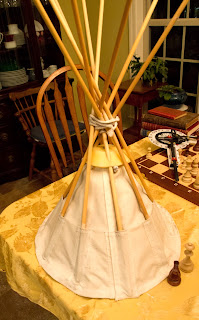
The other thing you may notice is that the smoke flaps allow rain to fall into the tipi. The smoke flaps can be manipulated at angles that will block most of the rain. However, the center, where the pole goes through, is not protected. For that, I made a "hat" with a "crown" of dowels that both keep the hat open in a cone shape, and give the aesthetic hinting at real tipi poles extending above the tipi.


Above is the canvas pattern for the tipi hat. I need to look again at the one I made, and write some instructions on how to sew it. I used a Pfaff sewing machine, because it is capable of sewing through 4-5 layers of canvas. Below is a CAD screenshot of my custom-designed, 3d printed parts for assembling the hat and webbing "poles" to the top of the 16' aluminum pole. The parts are available for download at Thingiverse.


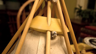
The webbing goes through the green "pole cap", which has a conical shape. I plan to rework this part, because the straps end up cracking the vertical features. There are five straps in all, creating ten "poles". The "cone" sits on the top of the rain hat. The "plug" is underneath, and the two are bolted together, sandwiching the canvas in between. The "cone" holds the dowels, which go into pockets in the canvas.


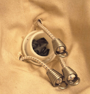
Below is a view inside the rain hat, showing three bungees feeding through the canvas around the "plug". They stretch down and hook into the holes in the part labeled "pipe", and hold the rain hat in place. In the above photo, you can see the knotted end of the bungee, as it feeds through the cone.


I made an "accessory ring" that locks into the groove where the aluminum poles join. It is useful for hanging things from. The ring clamp is in two sections, and locks in place when the accessory ring slides over the top of them. 


Monday, November 18, 2013

Harmonic Transformer Design Process

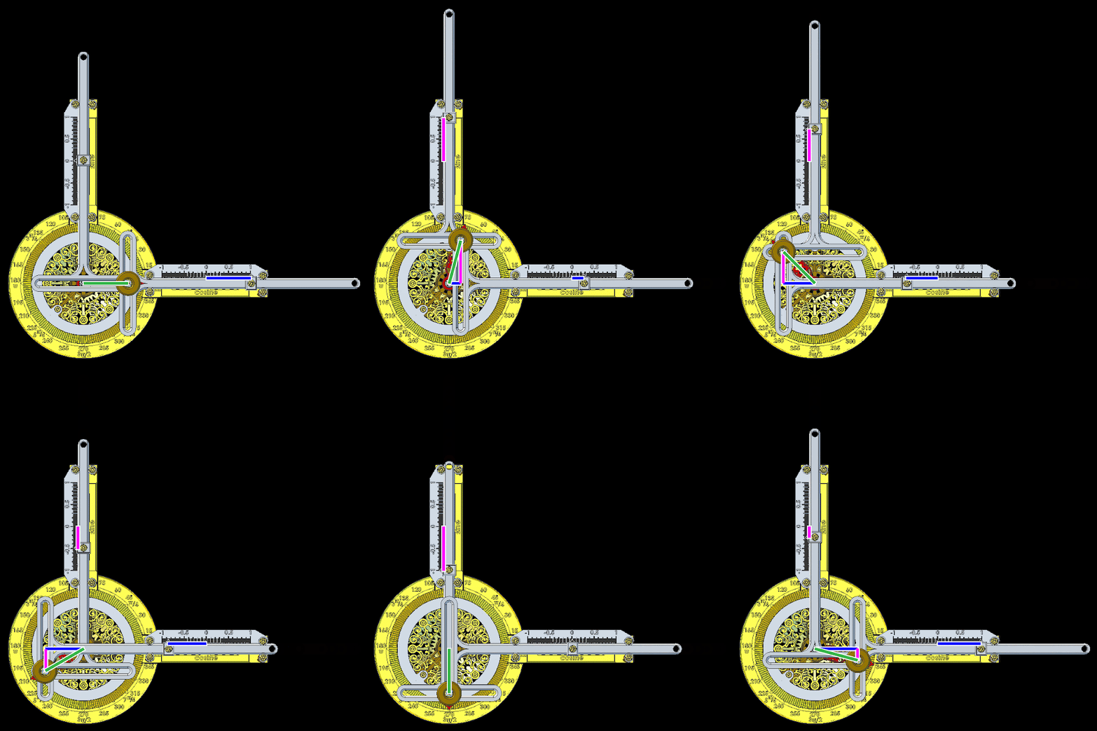
Here is a very brief snapshot of the design process for my Ideal Harmonic Transformer. The images are pulled from my various blog posts, where more detail is provided. I hope this gives you insight into the process of developing a design. Time, patience, and iteration are required.


Sunday, November 17, 2013

Harmonic Transformer for the Classroom

Treat yourself and your classroom to a machine that shows you how Sine and Cosine relate to angles.  Get the stl model files Here, or check them out in Onshape, where you can make mods, if you want.


How to use: 
Use the knob to rotate the arm to an angle. Read the value on the Sine and Cosine scales. Sine and Cosine values are given for a circle with a radius of 1, which is also called a "unit" circle. To obtain lengths for a circle with a radius other than one, multiply the reading from the machine by the desired radius.


Sine and cosine are trigonometric functions of an angle, defined by using right triangles. In the animation above and the figure below, a right triangle has been drawn on top of the Harmonic Transformer. The angle below is set to 30°. The hypotenuse is the radius of the circle, shown as a green line. The hypotenuse/radius is drawn from the arm's pivot center to the center of the knob, where the yoke pin is. The blue horizontal line is the "adjacent" side of the triangle, and the magenta vertical line is the "opposite" side. Notice that the blue side is the same length as the reading on the cosine scale. Similarly, the magenta side is the same length as the reading on the sine scale.


Assembly Instructions
Step 1
Print and clean up the five model files, shown below. These are sized to fit the print volume of the MAKERBOT® REPLICATOR 2®: 11.2L x 6.1W x 6H. The dome is optional, but adds character and protects the "key" nut. Note that the files with "-raft" in the name need to be printed with a support raft. The other model files do not require a raft.


Step 2

Slip the bezel ring screws (csink head) through the bezel ring, and loosely thread into the support base. Make sure the notch in the support base is oriented as shown in the figure.

Step 3

Piece together and slip Dome Capture Segments between the Support Base and Bezel Ring, as shown. The Support Base should fit into notches in the Dome Capture. Do not tighten the screws yet.

Step 4


Carefully turn the assembly over, and slip the Bezel sections under the Bezel Ring. The Bezel Ring will lock into the groove in the Bezel segments. Tighten all three screws until snug.

Step 5


Fit the Mount Extensions onto the Support Base, taking care to put the Sine and Cosine in the proper locations. Lock them together using the Support Bushings, as shown. Both Hi bushings go on one Extension, and Lo's on the other. Either way is fine. Make sure to use the correct length screw, and slip an angle roller under each screw. Slip a Scale Clip into place on each before tightening the screws. Leave the screws out or very loose on one side for now.

Step 6

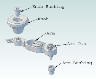
Push Knob Bushing all the way into the knob until seated. A very small amount of the bushing should show through the bottom.

Push the Arm Pin all the way into the Arm. Push the Arm Bushing onto the part of the Arm Pin that extends through the bottom. The Arm Bushing should contact the bottom of the Arm.

Step 7

Insert the Yoke Pin into the Arm until flush. Insert the Arm Pin into the hole in the center of the support base. Push the Gear Blank onto the Arm Pin, then secure into place with the Key, either the Rounded or Heart version.

Step 8

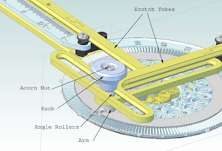
Assemble Yokes, et all onto the Yoke Pin, as shown in the picture. The Angle Rollers create a v-track for the inside of the Scotch Yokes. Tighten the Acorn Nut.

Step 9

Slide the Zero Scales onto the Yoke arms, and secure each with a Zero screw, adjusting them to point exactly at the 1 and 0 when at the extents of travel. Lay the lower Yoke into the Low Bushings, and secure with Angle Rollers and Low Bushing Screws. The Rollers and Bushings create a v-track for the Yoke to slide in. Secure the higher Yoke in the same manner, on the High Bushings.

Step 10


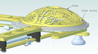
Align the Dome notches with the assembly, slip it into the Dome Capture Ring, and rotate it clockwise until it stops. I found it helpful to line up the screw holes first, then look at the notch that lets it fit over the support base/mount extension frame. Then clock it to the other edge of that notch, carefully push the dome edge into the slot, and clock it back until the holes line up again. I found it to be tricky, and might try wetting the edge lightly with water next time, to slightly lube it. Insert the Dome Screw to secure the dome in place.


All Done! Now start reading the sines and cosines of those angles!

My Printer in Action

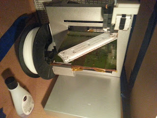
I have one of the original Up! printers. Here are some photos, and notes on how I have it set up.

The print table has a bumpy surface (paint from the factory), and is covered with kapton tape. Prior to printing, I give the surface a quick wipe-down with acetone (fingernail polish remover) to clean the surface. This has been working well for me. The part clings to the table while printing, then peels off fairly easily with a spatula.

I made an enclosure out of an old cardboard box, tape, and a sheet of acrylic that slides across the front as a door. There is an opening in the top with an air conditioner filter covering it. The enclosure keeps the machine warm, which improves print quality. It also makes it quieter. The filter keeps down the aroma of melted PVC.


The door is off in the video below. It is very quiet when the door is on.


When the part breaks free from the table during the print, the results are pretty disastrous.